|
Electronic Components Datasheet Search |
|
|
Electronic Components Datasheet Search |
|
BS640HD9V Datasheet(PDF) 37 Page - Advanced Micro Devices |
|
|
|||||||||||||||||||||||||||||
BS640HD9V Datasheet(HTML) 37 Page - Advanced Micro Devices |
|
|
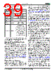
37 / 89 page  May 10, 2006 27024B3 Am29BDS128H/Am29BDS640H 35 D A TA SH EE T Standard Handshaking Option For optimal burst mode performance on devices with the standard handshaking option, the host system must set the appropriate number of wait states in the flash device depending on the clock frequency. Table 16 describes the typical number of clock cycles (wait states) for various conditions with A14-A12 set to 101. Table 16. Wait States for Standard Handshaking * In the 8-, 16- and 32-word burst read modes, the address pointer does not cross 64-word boundaries (addresses which are multiples of 3Fh). The autoselect function allows the host system to determine whether the flash device is enabled for ha ndsha king. See t he “Auto s elect Co mmand Sequence” section on page 36 for more information. Read Mode Configuration The device supports four different read modes: contin- uous mode, and 8, 16, and 32 word linear wrap around modes. A continuous sequence begins at the starting address and advances the address pointer until the burst operation is complete. If the highest address in the device is reached during the continuous burst read mode, the address pointer wraps around to the lowest address. For example, an eight-word linear read with wrap around begins on the starting address written to the device and then advances to the next 8 word boundary. The address pointer then returns to the 1st word after the previous eight word boundary, wrapping through the starting location. The sixteen- and thirty-two linear wrap around modes operate in a fashion similar to the eight-word mode. Table 17 shows the address bits and settings for the four read modes. Table 17. Read Mode Settings Note: Upon power-up or hardware reset the default setting is continuous. Burst Active Clock Edge Configuration By default, the device will deliver data on the rising edge of the clock after the initial synchronous access time. Subsequent outputs will also be on the following rising edges, barring any delays. The device can be set so that the falling clock edge is active for all synchro- nous accesses. Address bit A17 determines this set- ting; “1” for rising active, “0” for falling active. RDY Configuration By default, the device is set so that the RDY pin will output VOH whenever there is valid data on the outputs. The device can be set so that RDY goes active one data cycle before active data. Address bit A18 deter- mines this setting; “1” for RDY active with data, “0” for RDY active one clock cycle before valid data. In asyn- chronous mode, RDY is an open-drain output. Configuration Register Table 18 shows the address bits that determine the configuration register settings for various device func- tions. Conditions at Address Typical No. of Clock Cycles after AVD# Low Initial address 7 Initial address is 3E or 3Fh (or offset from these addresses by a multiple of 64) and is at boundary crossing* 7 Burst Modes Address Bits A16 A15 Continuous 0 0 8-word linear wrap around 0 1 16-word linear wrap around 1 0 32-word linear wrap around 1 1 |
|
Link URL |
| Does ALLDATASHEET help your business so far? [ DONATE ] |
About Alldatasheet | Advertisement | Datasheet Upload | Contact us | Privacy Policy | Link to Datasheet | Link Exchange | Manufacturer List All Rights Reserved©Alldatasheet.com |
| Russian : Alldatasheetru.com | Korean : Alldatasheet.co.kr | Spanish : Alldatasheet.es | French : Alldatasheet.fr | Italian : Alldatasheetit.com Portuguese : Alldatasheetpt.com | Polish : Alldatasheet.pl | Vietnamese : Alldatasheet.vn Indian : Alldatasheet.in | Mexican : Alldatasheet.com.mx | British : Alldatasheet.co.uk | New Zealand : Alldatasheet.co.nz |
|
Family Site : ic2ic.com |
icmetro.com |
 English ▼
 English
 Chinese
 German
 Japanese
 Russian
 Korean
 Spanish
 French
 Italian
 Portuguese
 Polish
 Vietnamese
 Indian
 Mexican
 British
 New Zealand