|
Electronic Components Datasheet Search |
|
|
Electronic Components Datasheet Search |
|
ISL854102DEMO2Z Datasheet(PDF) 13 Page - Renesas Technology Corp |
|
|
|||||||||||||||||||||||||||||
ISL854102DEMO2Z Datasheet(HTML) 13 Page - Renesas Technology Corp |
|
|
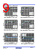
13 / 21 page  ISL854102 FN8870 Rev.1.00 Page 13 of 21 Mar 15, 2019 Detailed Description The ISL854102 combines a synchronous buck PWM controller with integrated power switches. The buck controller drives internal high-side and low-side N-channel MOSFETs to deliver load current up to 1.2A. The buck regulator can operate from an unregulated DC source, such as a battery, with a voltage ranging from +3V to +40V. An internal LDO provides bias to the low voltage portions of the IC. Peak current mode control is used to simplify feedback loop compensation and reject input voltage variation. User selectable internal feedback loop compensation further simplifies design. The ISL854102 switches at a default of 500kHz. The buck regulator is equipped with an internal current sensing circuit and the peak current limit threshold is typically set at 1.6A. Power-On Reset The ISL854102 automatically initializes upon receipt of the input power supply and continually monitors the EN pin state. If EN is held below its logic rising threshold, the IC is held in shutdown and consumes typically 2µA from the VIN supply. If EN exceeds its logic rising threshold, the regulator enables the bias LDO and begins to monitor the VCC pin voltage. When the VCC pin voltage clears its rising POR threshold, the controller initializes the switching regulator circuits. If VCC never clears the rising POR threshold, the controller does not allow the switching regulator to operate. If VCC falls below its falling POR threshold while the switching regulator is operating, the switching regulator is shut down until VCC returns. Soft-Start To avoid large inrush current, VOUT is slowly increased at start-up to its final regulated value. Soft-start time is determined by the SS pin connection. If SS is pulled to VCC, an internal 2ms timer is selected for soft-start. For other soft-start times, connect a capacitor from SS to GND. In this case, a 5.5µA current pulls up the SS voltage and the FB pin follows this ramp until it reaches the 600mV reference level. The soft-start time for this case is described by Equation 1: Power-Good PG is the open-drain output of a window comparator that continuously monitors the buck regulator output voltage from the FB pin. PG is actively held low when EN is low and during the buck regulator soft-start period. After the soft-start period completes, PG becomes high impedance if the FB pin is within the range specified in the “Electrical Specifications” on page 8. If FB exits the specified window, PG is pulled low until FB returns. Over-temperature faults also force PG low until the fault condition is cleared by an attempt to soft-start. There is an internal 5MΩ internal pull-up resistor. PWM Control Scheme The ISL854102 employs peak current-mode Pulse-Width Modulation (PWM) control for fast transient response and pulse-by-pulse current limiting, as shown in the “Functional Block Diagram” on page 5. The current loop consists of the current sensing circuit, slope compensation ramp, PWM comparator, oscillator, and latch. Current sense transresistance is typically 500mV/A and slope compensation rate, Se, is typically 450mV/T, where T is the switching cycle period. The control reference for the current loop comes from the error amplifier’s output (VCOMP). A PWM cycle begins when a clock pulse sets the PWM latch and the upper FET is turned on. Current begins to ramp up in the upper FET and inductor. This current is sensed (VCSA), converted to a voltage and summed with the slope compensation signal. This combined signal is compared to VCOMP and when the signal is equal to VCOMP, the latch is reset. Upon latch reset, the upper FET is turned off and the lower FET turned on allowing current to ramp down in the inductor. The lower FET remains on until the clock initiates another PWM cycle. Figure 33 on page 14 shows the typical operating waveforms during the PWM operation. The dotted lines illustrate the sum of the current sense and slope compensation signal. The output voltage is regulated as the error amplifier varies VCOMP and therefore varies the output inductor current. The error amplifier is a transconductance type and its output (COMP) is terminated with a series RC network to GND. This termination is internal (150k/54pF) if the COMP pin is tied to VCC. Additionally, the transconductance for COMP = VCC is 50µA/V vs 230µA/V for external RC connection. Its noninverting input is internally connected to a 600mV reference voltage and its inverting input is connected to the output voltage from the FB pin and its associated divider network. FIGURE 30. NEGATIVE CURRENT LIMIT, PWM FIGURE 31. NEGATIVE CURRENT LIMIT RECOVERY, PWM Measurements f SW = 500kHz, VIN = 24V, VOUT = 3.3V, TA = +25°C (Continued) LX 20V/DIV VOUT 5V/DIV IL 1A/DIV PG 2V/DIV 20µs/DIV LX 20V/DIV VOUT 5V/DIV IL 500mA/DIV PG 2V/DIV 200µs/DIV Time ms CnF 0.109 = (EQ. 1) |
|
|
Link URL |
| Does ALLDATASHEET help your business so far? [ DONATE ] |
About Alldatasheet | Advertisement | Datasheet Upload | Contact us | Privacy Policy | Link to Datasheet | Link Exchange | Manufacturer List All Rights Reserved©Alldatasheet.com |
| Russian : Alldatasheetru.com | Korean : Alldatasheet.co.kr | Spanish : Alldatasheet.es | French : Alldatasheet.fr | Italian : Alldatasheetit.com Portuguese : Alldatasheetpt.com | Polish : Alldatasheet.pl | Vietnamese : Alldatasheet.vn Indian : Alldatasheet.in | Mexican : Alldatasheet.com.mx | British : Alldatasheet.co.uk | New Zealand : Alldatasheet.co.nz |
|
Family Site : ic2ic.com |
icmetro.com |
 English ▼
 English
 Chinese
 German
 Japanese
 Russian
 Korean
 Spanish
 French
 Italian
 Portuguese
 Polish
 Vietnamese
 Indian
 Mexican
 British
 New Zealand